
Microsoft Visio is the drawing Application useful to draw simple flowcharts, to complex network diagrams. Through this article, I am going to explain how to create a basic flowchart using Microsoft Visio 2013 Application.
Step 1. Open Microsoft Visio 2013 Application. Click on the FILE menu, and then select New.
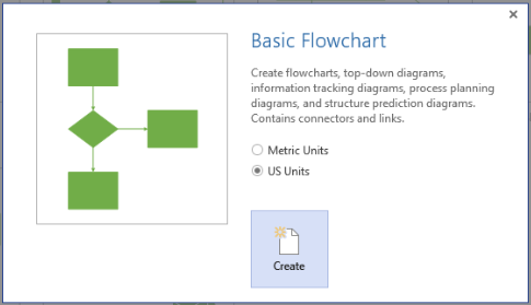
Step 2. Microsoft Visio displays a list of available templates to select to create the Visio diagram. We are going to create a flowchart diagram; so, select the “Basic Flowchart” template from the list of templates.
Step 3. Microsoft Visio displays a dialog to select the Units for the Visio diagram. This is an important selection; based on this selection, Visio will display the Drawing interface with selected Units. For example, if we select “US Units”, Visio will display the measurements of the shapes in inches.
I have selected “US Units“.
Once the selection is done, click on Create button.

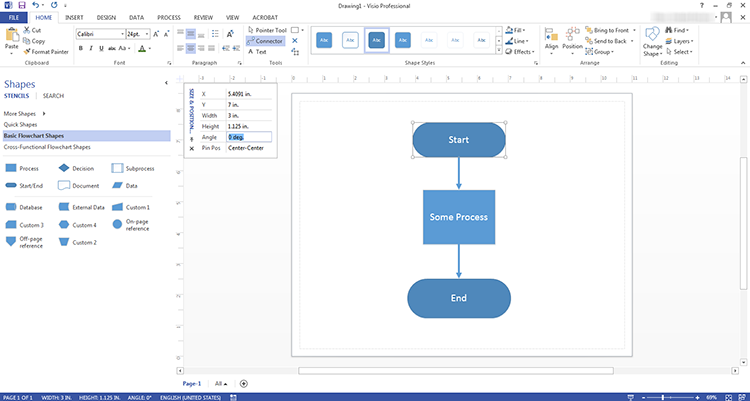
Step 4. Microsoft Visio 2013, displays a drawing window; where it displays a drawing page on the right side and, left side it displays a list of available shapes, under “Basic Flowchart Shapes”. These shapes we are going to use; to draw the Flowchart.
Step 5. Now we need to draw the Flowchart. Just, select the flowchart shape from the left side panel; drag and drop it on the drawing page. As we are drawing the Flowchart; which has Start & Endpoints. In between, processes, sub-processes or conditional flows, etc., will take place.
Drag the “Start/End” shape from the left side, and drop it on the drawing page.
Step 6. Once the shape is placed on the Page, double click on it (or press the F2 key) to enter the text in the shape. Enter “Start” text, as this is the start of the Flowchart.
Step 7. Now we need to place a process, to inform some process is happening in the flow. Drag “Process” shape and drop on the drawing page. You can enter the process for what it is meant for, by double click on it (or pressing the F2 key).
Step 8. Once the process is completed, we need to close the flow; by adding a “Start/End” shape to the drawing page. Change the text to “Stop“; indicates, the end of the flow. Observe that, for both Start & Stop; we use the same shape, but the text is different.
Now we have “Start”, “Process” and “Stop” flowchart shapes on the drawing page. Placing the shapes doesn’t mean anything unless we connect them with the connectors.
Step 9. It is important to connect the shapes, to understand, how the flow is going (from where to where). Select the “Connector” tool which is on the FILE menu, under the “Tools” group.
Once the “Connector” tool is selected, the mouse arrow will change to the connector icon; indicating that, you have selected the “Connector” tool to connect the shapes.
Step 10. Select one endpoint of the “Start” shape, and select another endpoint on the “Process” shape. This will draw a line between the two shapes. Observe also, where the Arrow is showing; the Arrow should be on the “Process” shape. Otherwise, the meaning of the flow will change.
Step 11. Repeat the “Step 10″, and now link “Process” and “Stop” shapes.

Step 12. You must save the drawing, by clicking on the “Save” icon (or pressing Ctrl + S key); which is on the top of the Microsoft Visio 2013 window.
That’s done. We have created a simple flow chart, with “Start” -> “Process” -> “End” flow.
I hope you liked this Article; please give the feedback through below Comments section.
🙂 Sahida